

Install documentation here
Description:
Smart Soft-Start power supply kit for the Adcom GFA-555, MKI or MKII. (Not for current SE or MS models.)
Typical over-engineering from Hoppe’s Brain! This robust and intelligent soft-start circuit monitors a number of conditions to ensure a proper soft-start action, and prevent circuit failure.
It mounts directly to the tops of the power supply capacitors, and is supported on the right side by adjustable feet.

Most soft-start circuits work by inserting a power resistor or thermistor in series with the incoming AC. This limits the inrush current. After a short delay, the inrush resistor is bypassed by shorting a relay around it. This works quite well, and is how my previous soft-start power supply for the GFA-555 worked.
However, this approach is not fail-safe! If, for example, you have a storm in your area, and are experiencing intermittent power outages, where the AC power keeps switching on and off, possibly at too low or too high voltage, then the inrush power resistor could overheat, or the relay might chatter and spark. If you have a “brown-out” situation where the incoming AC mains voltage is on but too low voltage, then the relay contacts may pull in weakly, and they will spark and burn. Simple timer-based soft-start designs tend to blow up in these scenarios.
I wanted to design a soft-start that could not hurt itself, or the amplifier in any adverse power conditions.
So I got to thinking… back to the basics: What is the actual purpose of the time delay?
It’s supposed to give the capacitors enough time to charge before engaging the bypass relay. But a simple timer only assumes that the capacitors are charged after a certain amount of time has passed. Why not actually monitor the current through the power resistor, before closing the bypass relay?
So that’s exactly what my circuit does. Current through the power resistor is monitored by sensing the voltage across it, via this arrangement of Zener diodes and an opto-coupler.
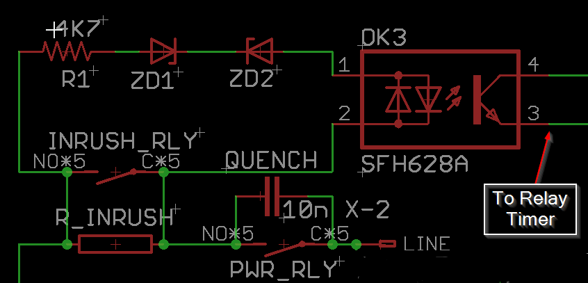
When the power is first engaged, the main power supply capacitors are drained completely, and so are essentially a short-circuit for a brief moment. At this moment, the voltage across the inrush power resistor is 120VRMS, or 170V peak, and this will drop rapidly as the capacitors charge. The LEDs in the opto-coupler will be on, because the voltage is high enough to pass through the zener diodes. The opto-coupler being on, inhibits the starting of the inrush relay timer. Once the voltage across the inrush power resistor falls below 56V, (meaning the capacitors are mostly charged) the opto-coupler turns off, and the timer starts to close the relay. Under no circumstances will the relay try to close unless the current through the power resistor is low. There will be no excessive sparking of the contacts, and the capacitors will be soft-started in all scenarios.
The circuit uses two 555 timer circuits, using one NE556 dual timer chip.
- The first timer delays the power relay until one second after the power switch is engaged. This makes the unit very friendly to audio systems that are switched on by a single power strip. Inrush current and switch sparking are reduced. The amp won’t draw any current for that first second, giving other audio components some time to start up and go through their own in-rush current spikes. Then, the amp comes on. This is all much easier on your power strip or power distribution unit.
- The second timer engages the soft-start bypass relay, only once the current through the soft-start resistor is low, and then after 1 more second has passed. The 1-second delay has nothing to do with waiting for the capacitors to charge. It’s purpose is to prevent relay chattering in the case of intermittent power. The relays will not switch on and off with a frequency any higher than 0.7Hz, under any circumstance, and I’ve tested a lot of scenarios to prove this!
The delay times do not need to be adjusted, no matter how large or small your main filter capacitors are. Larger capacitors will simply cause the circuit to engage slightly slower.
Fail-safes built in to the circuit:
- Low AC Mains voltage: Incoming AC mains voltage is monitored by another opto-coupler/Zener diode circuit. Incoming mains voltage must be higher than 95VAC before the circuit will start. This ensures that the relays will never be operated with less than their full 12V rated coil voltage. They will snap in and out firmly, without excess arcing.
- High Current through the inrush power resistor: If there is a fault in the amplifier, and it’s drawing excess current for some reason, the inrush bypass relay will not engage if the current draw is too high. (Too much voltage across the inrush resistor.)
- Overheating of the inrush power resistor: A thermal cutoff switch is attached to the body of the power resistor. If it gets hotter than 130C, the entire circuit is shut down until it cools off. This resistor will only overheat if something is wrong with the mains AC, or the amp itself is drawing too much current due to a fault.
- Power surges or high mains AC voltage: A MOV in parallel with the mains will clamp over-voltage and blow the mains fuse. (I still recommend using a good power conditioner/surge protector.)
- Relay chattering or incomplete engagement: Relays will only operate with full 12VDC coil voltage, and they will not click on and off any faster than 0.7Hz.
More Features:
- Remote Trigger Power Control. I got a lot of requests for this feature, so here it is! Many preamps output a 12VDC trigger voltage. No problem, but this remote trigger can accept anything from 3.3-24VDC. This makes it possible to control the amp with a computer, or micro-computer devices like an Arduino or Raspberry Pi. Input is by 3.5mm phone jack. The remote trigger circuit is galvanically isolated from the soft-start circuit by an opto-coupler, so there is no chance of creating another ground loop in your system.
- Low standby power consumption, 2.4W.
- Easier to install than the old version of my 555 power supply. The board mounts to the tops of the power supply capacitors, so no holes need to be drilled in the chassis. All existing wiring is retained, except that with the MK1, one of the power wires to the left-side output modules needs to be lengthened, and another shortened. (Wire included.)
- Everything is over-built! I use nothing but top-shelf components, even where it doesn’t really matter. Dale resistors everywhere… Kemet, On Semi, Panasonic, WAGO, TE Connectivity, Triad Transformers…. nothing generic. Everything is better than it needs to be. The 50W aluminum-cased power resistor barely gets warm in normal usage.The bill-of-materials cost on this product is really high, which is why the price is kind of high too. Oh well, that’s how I do.
- Additional bypass capacitor options: The boards comes equipped with the usual 0.1µF polypropylene bypass capacitors, but with additional 100µF electrolytic capacitors connected in parallel. This is done in an effort to keep ESR low across a wide frequency range. There is room to experiment and install your own combination of bypass capacitors. (Suggested viewing, EEVBlog Bypass Capacitor Tutorial.)
- Improved heatsinking of the bridge rectifiers. The heatsinks on the bridge rectifiers are over-sized, and keep plenty cool in operation.
- WAGO Cage-Clamp terminals used for all connections. These terminals are extremely reliable and simple to use. Just push the lever down with a small flat-bade screwdriver, and insert the wire. Their firm, spring-loaded connection will not come loose over time as the copper wire squishes down. They cannot be over or under-tightened, and the wire cannot come loose over time. The only reason you don’t see these terminals on more products is that they’re expensive.
- Double-thick, 2-oz copper clad PCB with plated through holes.
- Electrically safe design: All high-voltage, mains connected PCB traces, vias and pads, are kept isolated at least 2mm from each other, and at least 4mm from the amplifier power supply, or the soft-start power supply. Isolation slots are cut into the PCB to improve this further.
- Optional On-Board Fuse Holders for the GFA-555 MKII improve performance: This is kind of a big deal! One thing about the GFA-555 MKI that is better than the MKII, is that power supply wiring is much shorter. In the MKI, 16ga power wires run straight from the main power supply capacitors to the output modules. The rail fuses are mounted directly to the output module, so if you blow a fuse, you must open the top cover to replace it. In total, there is about 28″ of 16ga power wire used to hook up all four output modules. For the MKII re-design, Adcom moved these fuses to the back panel. This makes the fuses easy to change for the consumer, but their relocation adds literally FEET of extra 16ga power wire! In the MKII, power travels from the power supply capacitors, through about 10 inches of 16ga wire to the back panel fuse holders, then back out of the fuse holders through another 10 inches of wire to the output modules. That’s eight 10″ wires, for a total of 80″ of wire, just to hook up power to the output modules!All this extra wire adds inductance to the system, and significantly slows down the delivery of current from the power supply to the output modules and input board. This added inductance is why Adcom added 47µF local supply bypass capacitors to the output modules for the MKII. The MKI on the other hand, uses only 28″ of this wire to do the same job. Well, you can get this advantage back with my board! Just install the on-board fuse holders that are included with the kit. Remove the back-panel fuseholders, and install the included hole-plugs where the old fuseholders used to be.

- Independent and isolated power supply: The power supply for the soft-start circuit is an old-fashioned transformer with a LM7812 linear regulator. This was chosen over a cheaper switching power supply, for maximum reliability and long life, as well as the lack of switching noise from the power supply that might somehow make it into the audio. The soft-start circuit is galvanically isolated from the amplifier’s power supply, as well as the AC mains and the remote trigger circuit.
- Wide Capacitor Selection: Kit does NOT include main power supply capacitors, allowing you to make your own capacitor choices.You can:
- Use your existing, original capacitors. (They’re probably just fine) Some very early production units may have capacitors with solder tabs instead of screw terminals, and these are not compatible with the board and will need to be replaced.
- Buy new capacitors from a reputable source like Mouser or Digikey. Suggested part numbers provided in the documentation.
- Use something you already have in your parts bin! More details on selecting suitable capacitors are here in the documentation.
- Variac-friendly. A jumper allows bypassing the soft-start circuit so that you can test your amp on a variac. (Otherwise the soft-start won’t let the amp turn on until 95VAC.)
- Fun to build!
- So pretty!

Skills required:
This is an advanced electronics project, and you should be experienced in troubleshooting amplifiers.
Everything is clearly labeled and there are helpful texts written on both sides of the board.
Please read through the documentation to be sure this is a project you are comfortable doing.
There are some SMD components: They are large 1206 packages, so shouldn’t be too difficult to install. They save a huge amount of room on the board, so I went with them.
- (10) “1206” size SMD capacitors (3 different capacitance values)
- (1) Bridge rectifier.
Tools required:
You should have a reasonably well equipped electronics lab, with the usual assortment of hand tools, meter, scope etc. Specifically, you will need:
- A powerful, regulated-temperature soldering station: 50W or better! e.g. Hakko FX-888. This board really sucks the heat away from your iron, with its double-thick 2oz copper, and large polygon pours, some of which cover both layers. A weak soldering iron will make poor solder connections, and be frustrating to use. Components can be overheated due to the long time you need to hold heat to the work.
- A large soldering tip for heat-sucking areas like terminal blocks, relay contacts and the power resistor.
- A normal soldering tip for soldering SMD components.
- A tweezers for placing SMD components.
- Liquid or paste flux.
- 5.5mm and 7mm hex nut drivers.
- 2mm hex driver
- Solvents and tools to clean circuit boards; Alcohol and a brush, plus compressed or canned air to blow the solvent away. I use an ultrasonic cleaner with alcohol. All components can be submerged in liquid except the power transformer, so install that last if you want to submerge the board in solvent.
Support:
This is an advanced electronics project. You should have some experience repairing audio amplifiers. Please read through the documentation before ordering.
30 minutes free tech support is included with every purchase. Time beyond 30 minutes is billed at $75/hour. This includes time spent researching your issue, writing emails and talking on the phone.
I am happy to provide technical support, but please anticipate paying for for my time as part of the cost of your project. Tech support time is always billed, whether the issue is yours, mine or one of my suppliers.
Alternately, consider asking your question on a forum such as DIYAUDIO.COM. Send me a link and I may comment on the thread.
Documentation:
Please read this documentation before attempting this project, even if you’ve purchased a fully assembled and tested board.
Hoppe’s Brain BFA-555 Smart Soft Start Assembly Instructions