
This FAQ refers to classic Adcom products from the 80s and 90s, such as the GFA-565, GFA-535, GFA-545, and GFA-555, in MKI and MKII variations. It does not cover MOSFET amps like the GFA-5500, GFA-5800 or GFA-5802. Also, I have no experience with, or opinion on, currently produced Adcom products, or any official affiliation with the company. They seem nice though!
Index:
- My Adcom Amplifier makes a funny noise when I turn it on and off, is this normal?
- My Adcom amplifier makes a “POP” when I turn it on and off. Is this normal?
- WHY is there no speaker relay, or speaker protection circuit in Adcom amplifiers?
- Adcoms have no speaker protection circuit. Am I going to blow up my speakers?
- Are you ever going to offer a speaker protection board for Adcom amplifiers?
- My Adcom amplifier keeps playing music for a long time after I hit the power switch. Is that normal?
- How much DC offset is normal?
- Is my Adcom a “Mark 1” or “Mark 2”? (MKI or MKII)
- What’s the difference between the Mark I and Mark II? (GFA-535, 545 and 555)
- Which sounds better? The MKI or MKII?
- Where can I get fuses for Adcom amps?
- Bias Adjustment:
- Parts
- Should I replace the power supply capacitors? If so, which ones to get?
- Which Adcom amplifiers have leaking capacitor issues?
- How can I tell if the capacitors in my GFA-565 or GFA-585 are the bad ones?
- Is my GFA-565 or GFA-585 safe to use?
- How can I tell if my GFA-565 or GFA-585 is healthy?
- I’m a beginner with enough experience to be dangerous with a soldering iron, and I’ve fixed computers before. Can I replace my own amplifier circuit board?
- What are the most common issues with the GFA-5×5?
- How will a Hoppe’s Brain input board or power supply improve the sound of my Adcom?
- Transistor Matching – the Inputs and Outputs
- Should I leave my system on all the time? (No.)
- Where can I learn more about audio electronics repair?
My Adcom Amplifier makes a funny noise when I turn it off, is this normal?
Yes. These classic Adcom amplifiers have no speaker switching relays, and your speakers remain connected, even after you’ve turned off the power. As the power supply voltage slowly drains towards zero, there comes a point where the negative feedback collapses, things get all wobbly and the amp oscillates a bit. Not to worry, there isn’t enough energy left in the amplifier to damage your speakers. Some Adcoms do it, some don’t, and it is no indicator of the health of the amplifier. Consider it part of the amp’s personality.
The noise is usually a sort of “BWEEEEP!!”, “Mrrrrrp”, “ClickClickClick” or “BUP BUP BUP”.
My Adcom amplifier makes a “POP” when I turn it on and off. Is this normal?
Yes. Again this is due to the fact there is no speaker relay, so your speakers are connected as you hit the power switch. It takes a moment for the amp to stabilize. You may notice your woofer push back and forth a bit. Both channels should behave similarly.
However: If you see your woofer cone make an alarmingly large movement, or if it pulls in or pushes outward and stays there, turn the amp off immediately and check for DC voltage on the amplifier’s output.
WHY is there no speaker relay, or speaker protection circuit in Adcom amplifiers?
- Signal purity and reliability. Speaker relays are notoriously troublesome in classic audio gear. Contact corrosion builds up over time.
You may have observed that AC power relays used in high-current applications are extremely reliable. This is because power relays are designed to intentionally spark and spot-weld themselves closed in normal operation. This tiny spot-weld has very low resistance. Speaker relays don’t benefit from this sparking and spot-welding action, as there is usually little to no power going through them when they are switched on. - Cost. Adcom’s value proposition lies in using a small number of high-quality parts. Good speaker relays are expensive, and as mentioned, kinda crappy anyway. Side note: There are some really cool speaker protection designs out there using MOSFETS as speaker switches, and this is a very good idea.
Adcoms have no speaker protection circuit. Am I going to blow up my speakers?
Possibly!
These amps are 20-35 years old now. They do sometimes “go DC” and take speakers out with them.
However, these are super reliable amplifiers when they are properly maintained, and that is actually the best speaker protection there is. I’ve restored something like 200 Adcom amplifiers, and not a single one has blown out in the field. (Well there was that one GFA-545 that got hit by lightning, LOL.)
Also, it’s not entirely accurate to say it has no speaker protection. It does have rail fuses, and these can save your speakers in many cases. If you have efficient 8-ohm speakers, you can reduce the current rating of the rail fuses for more protection.
Are you ever going to offer a speaker protection board for Adcom amplifiers?
No, not really interested. There are plenty of designs out there.
My Adcom amplifier keeps playing music for a long time after I hit the power switch. Is that normal?
Yes. Again this is because there is no speaker protection relay, and so the speakers remain connected as the power supply capacitors slowly drain to zero.
How much DC offset is normal and how do I test for it?
DC offset should be measured with the input shorted, or a preamp connected and powered on. Having the input shorted simulates the effect of having a low-impedance source like a preamp connected. (You can make a shorting plug from an old patch cord, just cut the wire about 1″ long and solder the wires together.)
Installing well-matched transistors isn’t really about low DC offset, it’s about distortion. (Both transistors doing the same thing at the same time.) You may actually end up with more DC offset with a new set of matched transistors, as there is always some imbalance between NPN and PNP sides of the amp.
- GFA-535, 545, 555 MKI. Normal from the factory is about 40mV. With a pair of carefully matched input transistors, such as the ones I sell, you can expect less than 20mV. If you see much more than 50mV the amplifier should be checked out.
- GFA-535, 545, 555 MKII, GFA-565, GFA-585
These amps contain DC servo circuits, and so DC offset should be very close to 0V, whether you have the inputs shorted or not. Normal range is less than 5mV, and it may slowly drift around a bit. From a cold-start, your offset may be as high as 200mV, and should settle out to less than 5mV over a few minutes. (The DC Servo has a very slow time-constant so that it does not react at audible frequencies.)
Is my Adcom a “Mark 1” or “Mark 2”? (MKI or MKII)
Mark II amplifiers are labeled “Model GFA-5×5 II” near the power switch. If there’s no “II” then it’s a Mark I.
What’s the difference between the Mark I and Mark II? (GFA-535, 545 and 555)
- MKI is DC-coupled on the input, and the MKII has a capacitor inline with the input. I wouldn’t make too much of this difference. Both amps contain a capacitor in the input signal path. It’s just that the MKI puts the capacitor on the negative side of the long-tail-pair and the MKII puts it on the positive side, AKA the input.
- MKII contains a DC Servo circuit. An op-amp is used as a comparator. The DC offset from the amplifier’s output is fed into one leg of the comparator, and the other is referenced to signal ground. The comparator’s output is fed back into the input stage in order to nudge it one way or another to keep the amp’s offset close to 0V.
Note, this op-amp is not in the signal path. Each leg of the comparator is fed with an R-C network of 4.7Mohm into 0.1uF, and so has a time constant of about 0.3Hz, and only operates below this frequency to push the DC offset around. There is no music signal at its output. Do not substitute this op-amp in hopes of better sound. The original LT1006 (Often marked Adcom 3A) is a fine choice, as is the functionally equivalent AD820. The LT1006 is cheaper, and there is no need to spend extra money on the higher-grade bins of this part, with the lowest input offsets. It makes no real difference in this application. You should end up with less than 1mV offset anyway.
- The MKI has a two-transistor darlington output stage, and the MKII has triple-darlington. The triple darlington output stage, having an extra current gain stage, presents an easier load to the amp’s upstream stages. This has a number of design implications beyond the scope of this FAQ, but the often cited reason for its use in the MKII amplifiers, is better handling of low impedance loads. The MKI’s distortion rises more at low-impedance than the MKII, which is hardly affected. In practice, both MKI and MKII amps are fantastic with low impedance loads anyways. Some people prefer the MKI for its minimalism.
- MKII has a different output biasing scheme. The Vbe multiplier transistor, AKA bias spreader transistor is mounted on the output module heatsinks, and is connected with a cable back to the input board. It thermally tracks very nicely. The MKI has a somewhat pronounced positive thermal coefficient; it’s bias increases with heat, whereas the MKII remains pretty constant regardless of temperature.
- The GFA-555 MKII gets a canned and potted transformer, for lower noise, and it is physically very quiet too. (Not that the original is noisy.)
- Larger power transformers in GFA-545 and GFA-555: The original GFA-555 had a 700VA, and the MKII appears to be around 800 to 850VA. I don’t know how much larger the 545 MKII transformer is, but it’s physically larger and produces more power. If anyone has more solid data on this, let me know! The GFA-535’s power transformer remains the same size, but this is fine, as it’s already delivering 90W while only promising 60W! The 535 MKII transformer does get some additional shielding.
- More power in GFA-545 and GFA-555 MKII: Here are some typical maximum power measurements I have taken for all six GFA-5×5 amplifier versions. This is all at 1KHz and <0.1%, both channels driven.
GFA-535 MKI @8Ω 90W (Yes really!)
GFA-535 MKII @8Ω 91W
GFA-535 MKI @4Ω 128W
GFA-535 MKII @4Ω 130W
GFA-545 MKI @8Ω 118W
GFA-545 MKII @8Ω 134W
GFA-545 MKI @4Ω 171W
GFA-545 MKII @4Ω 212W
GFA-555 MKI @8Ω 240W
GFA-555 MKII @8Ω 266W
GFA-555 MKI @4Ω 338W
GFA-555 MKII @4Ω 390W - Nicer binding posts on the GFA-535 MKII. These crappy twist-lock terminals were replaced with standard binding posts.

I sell an adapter kit to replace these with nice binding posts.
- No “B Speaker” facility on the GFA-535 MKII. No speaker switches and associated lengths of wire. Just one set of binding posts.
- MKII gets nice “Tiffany style” gold-plated brass RCA input jacks instead of plastic.
- Fuses and wiring in the GFA-555 MKI versus MKII: The GFA-555 MKI has its rail fuses on the inside, and you must remove the top cover to replace them. The MKII moves the fuses to the back panel. That’s handy, but… This has a negative impact on the power supply wiring. The MKII has much, much longer DC power supply wires, due to the need to run them out to the back panel.
In the MKI, 16ga power wires run straight from the main power supply capacitors to the output modules. Rail fuses are mounted directly to the output modules. In total, there is about 28″ of 16ga power wire used to hook up all four output modules.
In the MKII, power wires run from the power supply capacitors, through about 10 inches of wire to the back panel fuse holders, then back out of the fuse holders through another 10 inches of wire to the output modules. That’s eight 10″ wires, for a total of 80″ of wire. The GFA-555 MKII contains 52 inches of extra power wire as compared to the MKI. All this extra wire adds inductance to the system, and slows the delivery of current from the power supply to the output modules and input board. This inductance is why the MKII adds 47µF local supply bypass capacitors to the output modules. This helps, but is not as good as having nice short power wires like the MKI.
This is why the Hoppes Brain BFA-555 Smart Soft-Start power supply kit has optional onboard fuse holders. You can put the fuses back inside the amp and shorten your wires up like the MKI. It’s the best of both versions.

I reckon the reason for the change to back-panel fuse holders was to make it easier for people to change the fuses, while discouraging them from opening up their amplifiers, and possibly getting shocked. Also, sometimes a user will be unaware there are fuses inside, and think that their amplifier is totally dead, when it only needs a fuse. It’s pretty common to find Adcom amps being sold “For parts” when all they need is a fuse.
Which sounds better? The MKI or MKII?
I don’t have a strong opinion on this. Both are excellent and sound very similar. The MKII seems to have just a little more “oomph”, probably due to the slightly larger power supplies, and easier-to-drive triple-darlington output stage.
Where can I get fuses for Adcom amps?
They don’t have them at the hardware store!
Fuse selection is very specific and there are many shades of “fast-blow” or “slow-blow”, so it’s important to get the right fuses. Vintage Adcom amps generally use either Littelfuse 314 series, or 312 Series, available at Mouser or Digikey and many others. 314 series is a little “slower” than 312, though they are both called “fast-acting”.
The part numbers are easy to decipher; The first three digits are the “Series Number”. For example a 314 Series 6A fuse is part # 314006.MXP or 314006.HXP the “MXP” and “HXP” are just packaging options, use either one.
Do not use 32V DC automotive fuses. Low-voltage fuses are not the same in the way they melt and arc when they blow out. Obviously don’t use aluminum foil or nails, LOL.
| Model | Power | Rail |
| *120V models, not including recent model Adcoms | ||
| *Sorry no data on MOSFET GFA-XXXX series. | ||
| GFA-535 MK1 | 312005 | 312004 |
| GFA-535 MK2 | 312005 | 312004 |
| GFA-545 MK1 | 312006 | 312004 |
| GFA-545 MK2 | 312006 | 312004 |
| GFA-555 MK1 | 312010 | 312006 |
| GFA-555 MK2 | 314012 | 312007 |
| GFA-565 | 314015 | 314012 |
| GFA-585 | 314015 | 314010 |
Bias Adjustment:
Test point confusion: Bias is adjusted by measuring the voltage, and thus current through the emitter resistors. The current through the emitter resistor is the same as the emitter current. Some Adcom service manuals specify a voltage as read across one emitter resistor, and others as read across two emitter resistors in series, which means the bias voltage specified in the manual is double the voltage across a single emitter resistor.
Example: GFA-535 MKI has its test points across one emitter resistor.
And the GFA-555 MKII has its test points across two emitter resistors in series.

But that only tells you the current through one or two output transistors. What we’re really interested in, is the average of all of them. Some will be below the spec, some above. I recommend checking every individual emitter resistor. Don’t bother with the test points. Connect the negative probe of your meter to the speaker POSITIVE output binding post—all of the emitter resistors have a common connection at the amp’s output—and then probe each power transistor’s emitter to read the voltage drop across each emitter resistor. Beware of probe slippage! I’ve blown way too many expensive output transistors that way. Now I use these Fluke extended fine point tips, and it hasn’t happened since. Alternately, put a piece of shrink-tube or tape over your probe so just the tip is exposed.
What I do is let the amp sit on the bench, with no clutter around it, with the cover on. From stone cold, I power-on and adjust bias to about 3/4 of the target value. This will climb as the amp warms up a bit. After 15 minutes or so, I’ll then re-adjust to spec. Then, put the cover back on and let it sit for about an hour to warm up. Check, adjust, check, adjust…. lather, rinse, and repeat as many times as needed. MKI amps in particular can take a long time to stabilize, take all the time you need.
You can also pre-heat the amp by running it into a dummy load, and then let it cool to a stable temperature.
What I’m looking for is that the bias hangs around the target, at room temperature with normal ventilation. The amp needs to come up to quiescent thermal equilibrium if it’s going to behave the same way in your audio rack. It takes a while to do it this way, but no big deal, I just let it sit on the bench and check it occasionally over the course of an evening.
Once adjusted properly, the heatsinks should feel just a little warm to the touch, about 100-110F. You can use an infrared thermometer to make sure both sides are approximately the same.
Bias specifications:
***Please just ignore test point pins on the circuit boards, they only cause confusion. All the emitter resistors have a common connection at the amp output. Take your readings from the amp’s positive output binding post to each output transistor’s emitter, which gives a reading across each emitter resistor.
These specifications are for bias voltage across any single emitter resistor.
| Voltage across single emitter resistor | |
| GFA-535 MKI | 5mV |
| GFA-535 MKII | 7mV |
| GFA-545 MKI | 6.5mV |
| GFA-545 MKII | 7mV |
| GFA-555 MKI (Early production runs with 0.47R emitter resistors) | 9mV |
| GFA-555 MKI (Most common type with 0.83R emitter resistors) | 16mV |
| GFA-555 MKII | 5mV |
| GFA-565 | 12mV |
| GFA-585 | 12mV |
Parts:

Should I replace the power supply capacitors? If so, which ones to get?
Actually, you probably don’t need to replace them, but it’s OK if you want to.
Large power supply filter capacitors in Class AB audio amplifiers are actually extremely reliable, due to the low stress they are under. A class AB amp consumes very little power at idle, and on average, spends most of its life operating at relatively low power, and thus low ripple current, across these very large, very high-ripple-current-rated power supply capacitors.
So these capacitors are basically breezing along most of the time. Many are still working fine after 40 years or more!
Capacitors in equipment that consume a lot of idle current—like class A amplifiers, or high bias current FET amplifiers—are under much more stress, and are more likely to be exhausted.
If your goal is maximum possible lifespan without a need for maintenance, then yeah, go for new capacitors. I usually do. However if you want to save a little money, you can keep the originals if they are still good, and spend your money on more important things.
The consequences of a power supply capacitor going out, are usually not so bad anyway. It doesn’t usually result in a damaging DC current at the speakers. Sometimes a hum will develop as an early warning and it should be checked out immediately.
How to do a basic test of your power supply capacitors:
This test shows at least that your capacitors have something like the capacitance they’re supposed to, which is a fairly good, but not definitive check on their health. Basically, we’re going to charge them up and watch how long it takes for them to drain after the power is removed.
Calculate the R-C time-constant of your capacitors in parallel with your drain resistors. τ = RC. This will tell you how long it should take for your capacitors to drop to 36.8% of their charged voltage.
Example: The GFA-555 has 15,000uF draining into 4.7K; a time-constant of 70.5 seconds. Rail voltage of the GFA-555 is ~83V, so 83V x 0.368 = 30.5V.
So you should see about 30V, 70 seconds after cutting the power.
Pull all four rail fuses out. Also , disconnect the power LED; it draws power from just one of the capacitors and will cause that capacitor to drain faster. Now that the amp is disconnected from its power supply, the only thing draining the capacitors, is the drain resistors. If all four caps have the same capacity, they should drain at approximately the same rate. Energize the power supply, switch off the power, start your stop-watch, and stop when the voltage drops to 36.8%. If any capacitor is more than 20% off from the others, they should all be replaced.
A better test: Get yourself an ESR meter like the DER EE DC5000. A fantastic tool for $125 or so.
Another good test: Drive the amp into a dummy load and observe the ripple waveforms across each capacitor with an oscilloscope. A bad capacitor will show more ripple than others. You can also use a true RMS voltmeter, or the one in your scope, to measure AC ripple under load.
Choosing capacitors for the GFA-555 MKI or MKII:
Without a soft-start, your maximum capacitance is limited by sparking of the power switch, and the rating of the fuse. I wouldn’t go over 4×22,000uF, and that’s already pushing more than OEM. If you do, buy some spare power switches and keep them around. It is possible to install an up-rated power switch if you are willing to enlarge the hole in the front panel. The original switch contains two sets of 16A contacts in parallel, and there are 20A or better rated switches out there. I don’t have a suggestion on a particular switch upgrade.
In the 15,000µF category, if you want to go easy on the switch… Unfortunately all the 15,000µF caps in this category are a smaller diameter than the original caps. They are all 2″ instead of 2.5″ like OEM, so if you get new ones, you’ll also need to install new capacitor clamps. The Nichicon LNR series LNR2A153MSE comes with the clamps, and has an excellent track record, I’ve used many.
Around 22,000µF I recommend the Kemet ALS series ALS30A223MF100
It fits in the original 2.5″ capacitor clamps.
If you are installing a Hoppe’s Brain BFA-555 Smart Soft-Start, or really any soft-start board, the sky’s the limit, so I recommend the Kemet ALS series ALS70A363MF100 36,000µF! That’s well past the point of diminishing returns IMO. Excellent quality caps and they look bad-ass. (Shown here wearing Hoppe’s Brain Capacitor Hats.)
Which Adcom amplifiers have leaking capacitor issues?
Don’t believe the rumors that all Adcoms have capacitor problems. It’s only the GFA-565 and GFA-585. Other models have rare and random capacitor failures, like anything else. Actually, there are relatively few electrolytic capacitors in the GFA-5×5 product line… fewer to go wrong than most designs. The GFA-535, 545 and 555 MKI contain only six electrolytic capacitors in total! MKII’s only have a few more.
How can I tell if the capacitors in my GFA-565 or GFA-585 are the bad ones?
If your amp has little brown mini-marshmallow-sized Elna “LongLife” capacitors in it, then there is a 100% chance they are bad. Elna is a good capacitor brand, but they had a bad formulation with these, and they have all since leaked.


Examine the area underneath the capacitors, and you may see corrosion on the PCB traces.

Is my GFA-565 or GFA-585 safe to use?
Unless it’s been properly fixed, no! All of these amps are at risk of DC voltage appearing at the speaker terminals. So many good speakers have been fried. :^(
Do not power-up an amp that still contains the brown Elna LongLife capacitors. The capacitors may explode and it is a foul, fishy odor indeed.
Properly fixing it is no easy task. The leaked capacitor electrolyte actually soaks into the fiberglass of the circuit board, and causes it to become ever so slightly conductive. Unfortunately, this just happens to occur in the same area of the board that contains all the high-impedance input circuitry, and so it is very sensitive to any stray currents. The input section develops a DC bias, and this is amplified and causes a large DC voltage to appear at the output.
It’s possible to fix the original board, with varying degrees of success. Many techs will attempt to clean the board, and sometimes this works, sometimes not. Often, an amp that appears to be fixed will develop problems down the road, as the electrolyte continues to diffuse and spread throughout the fiberglass substrate.
The best way to fix an original board is to “fly” all the high-impedance traces and component leads above the board. “Dead-bug” the input pins of the op-amp servo.
The best solution of all, is of course, a whole new board.
How can I tell if my GFA-565 or GFA-585 is healthy?
Fortunately, the DC servo provides a pretty good diagnostic indicator of the health of your amp. When a GFA-565/585 is sick, it will usually show an imbalance somewhere. The GFA-565/585 is a fully symmetrical design. Imagine there is a mirror sitting at 0V. You should see similar but opposite polarity readings at every point in the circuit, from the PNP side to the NPN side. Of course, transistors aren’t perfect, so some imbalance is to be expected. The Hfe curves of PNP and NPN transistors do not match very closely. That’s what the DC servo is for. Whatever inherent imbalance exists in the amp, is nulled by the servo.
So the amount of correction the servo needs to apply is a good indicator of the amplifier’s balance. The more out-of-whack it is, the more the servo will push out voltage in an attempt to correct it. The servo can swing about +/-13V from its +/- 13.8V power supply.
If you see something close to +/- 13V on the output of your servo, (Pin 6) you have a problem! That means the servo is trying as hard as it can to correct some imbalance, and failing. Normal range is -6V to +6V. In normal operation, this value may drift up to +/-0.5V
Speaking of the servo, it’s actions can seriously confuse troubleshooting of a DC offset! It can even cause a DC offset on its own, if is defective. Lift one leg of R116 to take it out of circuit, and fix the issue causing the offset. A healthy 565 will produce less than 1V offset without the servo. The EBFA-565 features a jumper to take R116 out of circuit.
A correctly operating GFA-565/585 will show less than 5mVDC on the output terminals. Anything more indicates a problem. If for example you have 100mV on the output; this isn’t dangerous to your speakers, but it means the servo is failing to fully compensate the DC offset.
Further checks:
Compare your amp with this Annotated Schematic for the EBFA-565. It’s loaded with troubleshooting tips, DC operating points and other measurements.
I’m a beginner with enough experience to be dangerous with a soldering iron, and I’ve fixed computers before. Can I replace my own amplifier circuit board?
Maybe! Unlike computer repair, amplifier repair is rarely as simple as a board swap. You’ll want to have some experience troubleshooting and repairing analog circuits. Very often a bad input board will also fry your output section, so the output section should always be thoroughly checked before installing a new input board, or the input board may be smoked again. This is not warrantied.
I do not recommend attempting a GFA-565 or GFA-585 as your first amplifier repair. These are fairly complicated amps which confound and frustrate experts at times. The GFA-555 on the other hand, is more minimalist in design, and easier to troubleshoot. (Both are excellent amps.)
What are the most common issues with the GFA-5×5?
Generally speaking, the Adcom GFA-535, 545 and 555, both MKI and MKII versions, are extremely reliable amplifiers. The GFA-565/585 is extremely reliable once properly repaired.
Contrary to popular belief, not all Adcoms are not prone to capacitor problems. It’s just the GFA-565/585.
A not-at-all unusual Adcom reliability anecdote: I have a 1986 vintage GFA-555 MKI that I got for free from a bar that was renovating. It sat on a shelf behind the bar for about 10 years, covered in greasy dust, driving a hodgepodge of various speakers scattered around the bar, …like 6 pairs of speakers all hooked in parallel with super long wires. The amp was rusty and dusty inside, and despite all of this abuse, it still worked perfectly! I cleaned it up, touched up some solder joints and ran it as a subwoofer amplifier for 10 more years. More recently I’ve fully restored it, and now it powers the bass drivers in my active speaker setup. This is not an unusual story; these amps are tough!
Common issues, in no particular order.
- GFA-555 MKI output driver transistors sometimes pop short and make the amp go DC to rail. These have just barely sufficient Vce ratings. The GFA-555 will swing nearly 170V rail-to-rail, and the 2SA1011 driver transistors are only rated at 160V. It’s likely the factory was testing and sorting transistors, binning them by VCE, and putting the higher-voltage ones in the GFA-555’s, and the lower voltage ones in the GFA-545’s. This is not Adcom being cheap! Back in the day, there was a small selection of transistors with good Ft, low capacitance and high-power dissipation, all in the same device. They didn’t have the luxury of modern devices like the MJE15032/33, which is my recommendation for replacement, and every 555 MKI should have this done.
Related issue – Thermal bias-compensation thermistors: There are 1K NTC thermistors glued to the NPN driver transistors. They can be pried off with a razor blade and re-used, or simply replace them with Epcos/TDK B57164K0102J000. Use super-glue to attach to the body of the transistors. (Yes, super-glue, this as as original and it works great.) - Speaking of transistors, if you have the original Toshiba 2SD424 and 2SB554 output transistors, and they still work, keep them! They’re really excellent, and new ones aren’t really much better. New ones do tend to match closer though, and if you buy a set with all the same batch codes on them, they’ll probably match really well without having to hand-match them.
- Power switches on GFA-555 MKI and MKII sometimes weld themselves shut, permanently on. The 555 has a pretty huge power supply with a massive inrush current; it’s a 700-850VA transformer going into 4×15,000uF, which is right up against the limit of the surge capability of the switch, which uses two sets of 16A rated contacts in parallel.
Fortunately this switch is still made, and is cheap as chips, so pick up a spare the next time you put in a parts order. Carling RGSCC901-R-B-B-E available at Mouser and others. (No affiliation)
Ahem, product plug, you can just get one of my soft-start power supplies and it becomes a non-issue. You can install larger power supply capacitors; the sky’s the limit, as long as they fit in the case. - GFA-555 MKI & MKII; Cracked solder joints on TO-126 transistors, due to overheating. Fix; Attach small heatsinks. Don’t over-do it. Large heatsinks stress the solder joints. A small heatsink is all it needs. Hoppe’s Brain input boards feature board-mounted heatsinks for these transistors.
- GFA-555 MKI & MKII; Blown or shorted TO-126 transistors, due to overheating. You might notice the board is browned in this area. These transistors should have small heatsinks installed.
- GFA-555 MKI RCA Jack shields come loose. Replace with Rean NYS367-0 (black) & NYS367-2(red)

- GFA-535 MKI & MKII; Bridge rectifiers sometimes overheat and blow out if the amp is driven hard for an extended time. They’re not heatsinked like those on the GFA-545 and 555. My power supply supply boards move the bridges to the floor of the chassis for heatsinking.


- GFA-555 MKII bias compensation transistor cables sometimes corrode, especially in humid environments. Corrosion is exacerbated by heat from TO-126 transistors nearby. This can cause DC to appear at the output, as it throws the bias spreader circuit out of whack. Replacement board header is JST B3B-XH-A(LF)(SN), plug housing XHP-3, and pins SXH-001T-P0.6
These connectors are a pain to solder by hand, so my BFA-555 MK2 circuit board kit comes with a set of these cables, even if you’re just buying a plain unpopulated board.
- GFA-555 MKII, GFA-565/585 Output module local supply bypass capacitors. These will be either 47µF or 100µF. Some amps came with rather small, mini-marshmallow size capacitors here, 100V usually, and these are under a good deal of stress and they sometimes leak. No worries, a little stray electrolyte is not a big deal on the output modules; everything is low-impedance, and the goo doesn’t get onto any signal traces, just power. Clean well and replace them.
Some amps came with larger 160V rated Panasonic caps, and these are usually OK. I replace them anyway.
I like Panasonic EE 100uF/160 volt EEU-EE2C101, 10,000 hour rated at maximum ripple. Yeah, they’ll be fine. - Somewhat rare issue: Some very early production GFA-555’s from 1985-86 used 80V rated power supply capacitors. The power supply runs at 83V! (Also, residential AC voltage has crept upwards since the 70’s.)
These caps may be branded TOWA or “Capacitor Technology” and have blue shrink wrap and solder tab terminals on them, to which the ground bus wire is soldered. It’s a good quality capacitor, but they slowly leak and dry up being run over-voltage like this. - GFA-565 capacitor leakage. Sadly this problem was no fault of Adcom’s, but it didn’t do their image any good. But it can make GFA-565’s dirt cheap to acquire, and a new board makes these amps a bargain for those willing to take on the project.
- Crystallized mica caps on GFA-555 II: Some—not all—GFA-555 II boards use wax-coated silver-mica caps. The wax is meant to keep moisture out, and away from the very easily corroded silver capacitor electrodes. In the GFA-555 II, these capacitors happen to sit right next to some transistors that run very very hot, and the wax melts and softens a little every time the amp gets warm, and cools when the amp is off. Eventually, crystals form, due to the thermal cycling. I haven’t actually seen any caps go bad because of this issue, but it can’t be good! This could cause a failure years down the road.

Note: The GFA-565 and GFA-585 also use these wax-coated mica caps, but they’re not located near anything hot, and they are no problem at all.
Also note: These caps should not be ultrasonically cleaned, or cleaned in any solvent that will dissolve wax.
New mica caps from Cornell Dubilier are epoxy-coated, waterproof and ultrasonic cleaning compatible. They’re also very expensive because they are becoming niche components and Cornell Dubilier has a monopoly on them now.
How will a Hoppe’s Brain input board or power supply improve the sound of my Adcom?
I don’t make a lot of wild claims about the sound of my mods. For one thing, these amps sounded great when they were new! I have never been able to actually compare a fully working, brand new Adcom against one of my refurbished ones. They come to my bench full of tired old components, so the chance to compare is lost—it is not operating as new anyway.
Many people describe the sound of a properly refurbished Adcom GFA-5X5 as “clean” or “effortless”. They clip gracefully, no rail sticking, oscillating or overshooting. They drive difficult loads easily; even the smallest Adcom, the GFA-535. The Adcoms are not “tube-like”. They are accurate bipolar transistor amps.
I’ve come to believe that the most critical factors for good sound in these amps are…
- The input transistors must be well-matched. They vary wildly from the factory. I suspect when people describe an Adcom as sounding “harsh”, it is largely due to badly matched input transistors.
- The driver transistors on the 555 MK1, besides being the number one failure mode of that model, (it’s still extremely reliable overall) are reputed to cause harsh sound, and that makes sense from an electrical standpoint as well. New ones are better in number of parameters.
- A Hoppe’s Brain input board. Two layer, plated through-hole PCB, wider, shorter traces, a ground-plane pour, integrated heatsinks. Better signal integrity, less inductance and lower impedance all-around.
- Local Supply Bypass Capacitors installed on the input board. (All Hoppe’s Brain boards have this feature.)
- Fuses moved from the back panel of GFA-555 MK2 to the inside of the amp, for much shorter power supply wiring. The Hoppe’s Brain Soft-Start power supply offers the option to move fuses internally.
- Last, but least. New capacitors. Audio-grade types for signal paths, high-endurance, high-frequency power supply types for power supply stuff. Polypropylene caps replace Polyesters in some signal paths. C0G ceramics or silver-mica for output section compensation caps.
Above all, the way to a good sounding amplifier, is taking the time to do it right. Good sound is a culmination of many small details.
Transistor matching:
The inputs:
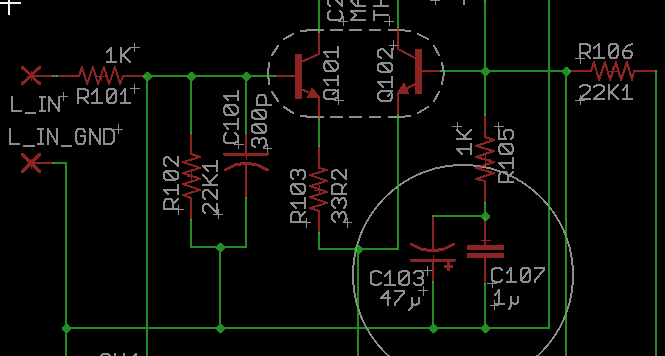
All Adcom GFA-5×5 amplifiers have a “Long Tail Pair” as the first stage, for example this GFA-535 MK1.
Here’s a good article explaining LTP’s, and here’s a good video.
In a nutshell, there is a constant current source—in this case Q605—and it provides current to both transistors. If both of these transistors are identical, everything will be balanced and they will share the current equally.
One side of the LTP is an inverting input and the other non-inverting. It’s pretty much the same thing as the input to an op-amp; most have this same arrangement inside.
For low distortion, both these transistors need to be doing the same thing at the same time, so they should be matched for Hfe at the desired operating current. For the GFA-5×5, this is approximately 1mA, and so that is the value I use to match the transistors I sell.

Matching input transistors:
Unfortunately it’s not as simple as sticking them in a transistor tester and reading the Hfe value. That only gives the Hfe at whatever current the tester happens to use, and at whatever temperature the semiconductor junction happens to be at the moment. Hfe (and Vbe) varies greatly with heat, and so the transistors must be kept at the same temperature while they are tested.
I use a transistor matching jig as described in this DIYAUDIO thread. (I am forum user Phloodpants on diyaudio.)
The jig is set up much the same as an LTP. There is a current source that feeds both transistors, and if they are balanced, you will see identical current across their collector resistors.
The Outputs:
The outputs don’t need to be matched as precisely as the inputs do.
If you buy output transistors from a reputable supplier, the transistors you receive will usually be all from the same batch code, and will usually match pretty well. Semiconductor manufacturing is super consistent these days.
The best way to match output transistors, is with a curve tracer that can put significant current through the device. I don’t have one. But you can also check the matching with the transistors installed in the amp.
Matching output transistors in-situ:
You’ll need:
- A meter that can read True RMS AC voltage to at least 20KHz.
- Signal generator
- Dummy load
We’re going to measure the current through each output transistor, by measuring the RMS AC voltage developed across the emitter resistors, while the amp plays into a dummy load. It’s been my experience that the 5% tolerance emitter resistors that Adcom used, actually measure better than 2% of each other, so they can be used as a pretty accurate measurement of emitter current.
Check matching at idle: This is a DC measurement. Bias the amp as normal, and read the DC voltage across each emitter resistor. The easiest way is to just stick one meter probe into the amp’s positive output binding post, and the other probe goes to each transistor’s emitter. It can be hard to reach all the transistors without shorting anything so I recommend these extended fine-point probe tips from Fluke.
The matching is generally worse at idle than it is at higher power. This is because the transistors are just barely on, and the beta of big power transistors varies a lot at low current. For example, the GFA-555 MKI has 0.82R emitter resistors, with a spec of 16mV bias across them (20mA), and with the original Toshiba output transistors, these will range from about 14-20mV. It’s not unusual or unexpected to have 10-20% range here, and how much you consider a problem is up to you.
Check matching at low, medium and high power:
Now we do AC current measurements. Hook up your 8-ohm dummy load. Apply a 1KHz sine wave to the input, enough to generate a 5VRMS output. With your true-RMS meter, measure the AC voltage across each emitter resistor. This will be proportional to the current running through that transistor. Compare to the others. Calculate their percentage delta from each other. You should be seeing better matching than you did at idle, and they should match within 5%.
Now try 1/3 power, 2/3 power and full-power. You should still be getting better than 5%.
Any transistors that don’t match well enough, swap them out and try again.
Should I leave my system on all the time? (No.)
There is a common belief in audio circles, that one should leave a system on 24/7 for best sound. Warm-up is often cited as the reason, and while that is a feasible theory with some equipment, I can say that Adcom amps and preamps will all come up to a stable operating point within 20 minutes of power-on, usually much less. The circuit does not need to come up to full quiescent temperature in order to perform properly.
The other oft-cited reason for leaving equipment on 24/7 is reliability; the idea being that the heat-cycling causes thermal stress on components and solder joints. This is, in my opinion, unfounded. If you have components in your gear that get so hot that it cracks solder joints, the last thing you want to do is leave such a hot-running device powered on, baking all day and night. There are other components that will be affected by that heat, and will experience accelerated aging, especially electrolytic capacitors. Every 10C rise in temperature cuts the life of a capacitor in half. (Roughly)
Where can I learn more about audio electronics repair?
Not affiliated with anyone listed here, not being paid or anything, but I recommend, in no particular order…
- Books and technical bulletins. The Art of Electronics. Anything Jim Williams. Anything Walt Jung.
- Fran Blanche, Franlab! So much cool vintage electronics! Fran’s guitar effects pedals are legendary.
- John Audio Tech on YouTube.
- Mr. Carlson’s Lab on YouTube. Mr. Carlson has a gift for teaching, and apparently infinite patience to do a job right. His lab is packed wall-to-wall with the coolest vintage test gear you’ve ever seen.
- Rod Elliot. Check out his “Troubleshooting and Repair Guide”.
- XRayTonyB on YouTube. Super deep dives into cool vintage audio electronics projects, and explorations of some rarely discussed electronics theory. Tony did a 3-part series on his repair of an Adcom GFA-585 using my circuit boards! It’s a must-watch if you’re doing a GFA-565/585 repair. (Again, no affiliation, he bought boards from me like anyone else.) His videos are unhurried, and long, but in a good way! Because you’ll definitely learn a lot, and you’ll know it well.
- Dave Jones, EEVblog. Goes without saying. Entertaining, curious and full of great advice, tutorials, tear-downs, etc. I’ve learned so much about PCB layout from Dave’s videos.
- CuriousMarc. The Apollo guidance computer restoration project, is a tour de force of nerditude. Also if you have a “thing” for HP test equipment, this one’s for you.