


Price range: $80.00 through $480.00
- Adcom GFA-565 replacement circuit board.
Description
NEW VERSION! (October 2022) Based on customer feedback, I present this completely new, improved input board for the Adcom GFA-565. This version is substantially easier to build, install and troubleshoot, and its performance is a little better too. If you really want the old version, which looks more like the original board, I still sell the original BFA-565 board, here you go.
This is the cure for leaky capacitors and DC offset problems in the original Adcom GFA-565! Nearly every GFA-565 ever made was affected by a bad batch of leaky capacitors that cause speaker-blowing DC offset to appear on the output. You can try to clean up the original board, but the DC offset issue often persists. The electrolyte actually soaks into the fiberglass, making it ever-so-slightly conductive. This affects the balance of the high-impedance circuitry around the input stage and DC servo. Amps that seem fixed can actually develop DC offset later on, as the electrolyte continues to spread through the fiberglass. It’s a frustrating problem to work on. A new board is the best solution.
Features:
- Optimized, symmetrical PCB layout: The GFA-565’s circuit—designed by the legendary Walt Jung—is a picture of perfect symmetry; A complementary mirror-image from positive to negative halves. The new layout reflects this symmetry. It is made larger than the OEM board, and arranged in a more symmetrical fashion. Impedances seen by the circuit, that are caused by the board, are therefore more evenly balanced. (NOTE: The OEM board is a perfectly good design, but it’s single-sided and they would have been under budgetary pressure to make it small, or to meet a certain size so they can get a large number of boards on a panel. Thus, the OEM board is a bit cramped. Again—not complaining—Adcom’s circuit board quality was better than similarly priced competition at the time.)
- Solder-less installation and removal: Something I kept hearing from customers, is that if something goes wrong and the magic smoke escapes, and the board needs to come out for repair… Ugh, all the wires need to be de-soldered, and it’s hard to reach them without burning components, wires, or chewing up the PCB pads. It’s a little awkward to work with the older board with so many solder connections, and it’s a major bummer to have to re-do them every time the board needs to come out. On the EBFA-565, all connections that used to be solder-pads, are now right up front on WAGO cage-clamp terminal blocks. These spring-loaded clamps grip the wire very, very firmly, and make an oxygen-tight connection that will never come loose. (Screw-terminal blocks can come loose over time as the copper squishes.) The board can be removed for troubleshooting or repair in a few minutes, and reinstalled with no damage to PCB pads. …so much better. And it makes the wiring neater too.

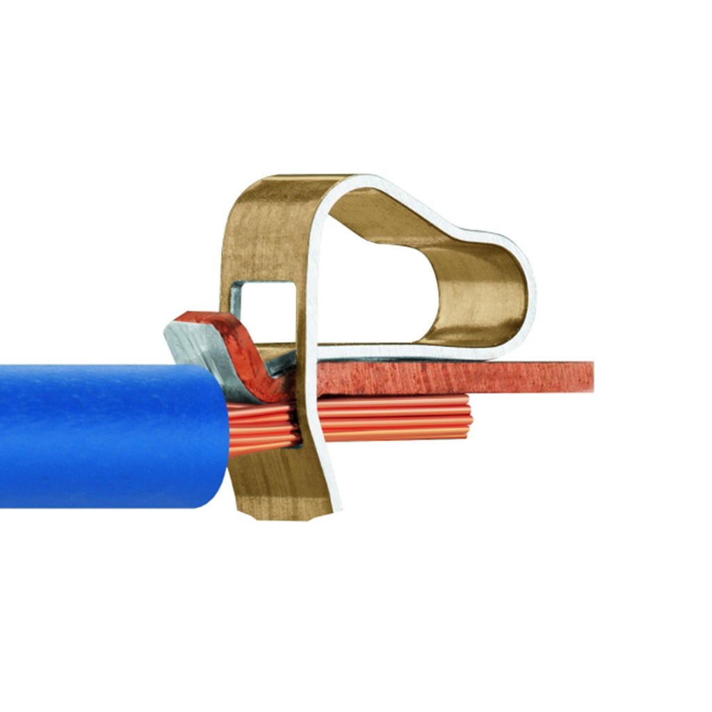
Inside a WAGO Cage-Clamp - Top-shelf components throughout: Kits and pre-assembled boards come with Dale RN and CMF resistors, 0.1% tolerance resistors in key locations, polypropylene capacitors, high-endurance electrolytic capacitors, silver-mica capacitors, etc… The good stuff.
- Compatible with old parts from the original board, so if you are building up from a blank board, you may recycle many of the un-damaged original parts. (With a few exceptions, see below)
- Two-layer, plated through-hole FR4 fiberglass circuit board.
- Traces are routed on the top and bottom layers.
- Ground planes cover the top and bottom layers.
- High-impedance traces are given wider isolation from ground planes, other traces and pads.
- Symmetrical layout makes it easier to build, and less error-prone, because it’s easier to locate the components.
- More room to work: Things are less crowded. It’s easy to probe any point on the board, and it’s easier to assemble and re-work.
- Clear labeling: Every component is labeled with its part number and value.
- An annotated schematic, loaded with troubleshooting tips, DC operating points, etc, is included with the board, printed on tabloid sheet 11×17 paper. Download it here.

- Convenient test points for measuring the most important circuit parameters, referred to expected values on the schematic.

- Improved heatsinking. The TO-126 VAS transistors in the original design run very hot. The heatsinking of this new design is much more effective and keeps temperatures below 60C.
- Bypass caps are added to the +/-13.8V supplies
- A 0.1uF polypropylene bypass cap has been added in parallel with the 10 ohm isolation resistance between amp ground and the input section. This improves high-frequency coupling between these ground potentials. This feature was added in response to a customer who experienced oscillation because of substituting a wire-wound resistor in this position. The added inductance was causing the oscillation, and a metal-film resistor fixed the issue. If a little bit of inductance can cause this issue, I figured that adding a bypass cap in parallel would prevent that potential issue, and it may improve performance a smidge.
- Includes new cable assemblies for signal input, bias compensation transistors mounted on the heatsinks, and bias enable from the soft-start board. These cables are often corroded from capacitor leakage, or life in a humid environment. New cables are pretty essential for a good restore job, but they are difficult to make by hand because the connector pins are meant to be crimped by a special machine. I had these cables specially manufactured to include with EBFA-565 boards.

- Small-signal transistor Compatibility: Some transistors are no longer available in the original ECB pinout, so the EBFA-565 also accommodates new transistors with either EBC or CBE pinout. (KSP42/92 and BC550/560, respectively.)


- STABISTORS: These components are rare and getting rarer, so the board supports three types of stabistors.
- OEM through-hole KB262 and KB362. (Little epoxy blobs) You may re-use them if their leads are not corroded. Caution: Anode is marked with black stripe instead of cathode as you would expect. Double-check with multimeter diode-check function.
- Some 565’s came with unknown, unlabeled stabistors that look like 1N4148’s, but will show 1.2V and 1.8V drop on diode check. (2 and 3 junctions) These are legit and can be re-used.
- CMXSTB400 SOT-6 SMD -EOL.

- Nexperia BAS17,215 Discontinued in 2025 but may still be available. Single-diode SOT23 package, and you need 10 diodes for a board. Fortunately SOT23 is pretty easy to solder for SMD.


Deleted features:
-
- 2-pin JST Board Header Connectors J101 and J102: These are meant to provide power to the exceedingly rare balanced input option board. If someone wants to install an EBFA-565 board into a balanced input GFA-565, these power connections can be bodged in, using test points as pads for connecting power wires.
- 2-pole pin header J109: Connected across the 4.7uF input capacitor. I think this was used for production testing and is not needed.
Performance:
Performance of the EBFA-565 is slightly improved over the BFA-565, which itself, is almost certainly an improvement over the OEM board. I can’t definitively prove this because I have never tested a working OEM board, as they are all so ruined. However, the measurements I have taken can be compared to those in the service manual, and to measurements taken by others. This article goes into details of my performance validation testing, and the results are excellent as expected.
EBFA-565 versus BFA-565 (Validating a new design)
Skills Required:
Documentation:
These two documents explain the scope of the work. Please review before purchasing a board. https://hoppesbrain.com/ebfa-565-assembly-and-installation-guide/~AND~
https://hoppesbrain.com/gfa-565-circuit-board-replacement-notes/
Support:
30 minutes tech support is included with every purchase of a board kit. Time beyond 30 minutes is billed at $75/hour. This includes time spent researching your issue, writing emails or talking on the phone. I am happy to provide technical support, but please anticipate paying for for my time as part of the cost of your project. Tech support time is always billed, whether the issue is yours, mine or one of my suppliers. Alternately, consider asking your question on a forum such as DIYAUDIO.COM. Send me a link and I may comment on the thread.
Parts:
All parts available from Mouser, Digikey and other suppliers. (No affiliation)
EBFA-565 Parts List
That’s absolutely everything you’ll need, not just for the input board, but for a thorough refurbishing of the whole amplifier, including power supply capacitors, higher-voltage driver transistors, parts for the soft-start board, power switch, etc. Likely, you can re-use many original parts to save money. I also sell matched sets of input transistors, along with their cascodes, 8 matched transistors in total for $40. (When you buy a board.) Getting set up to match transistors is a significant project in itself, so I sell matched sets. My methodology is based on this discussion at diyaudio.com. You can reuse the original transistors if they are good, but they often have electrolyte goo on their leads, so if you do re-use the originals, make sure you clean them really, really well, and that the leads are not corroded. Corrosion from electrolyte contamination can work its way up the leads of components, and into the body of the device.
Parts that cannot be recycled from an old GFA-565 board:
These things are either new or different on the EBFA-565. If you are buying a bare board and sourcing your own parts, or recycling old parts from a GFA-565 board, you will need at minimum:
- Heatsinks: 2x Aavid Thermalloy 513002B02500G
A common heatsink profile, there are many substitutes. - C123, C124 WIMA MKS2C031001A00MC00 0.1uF 63V 5mm L/S
Non-existent on OEM board. Substitute any good poly cap. These are power supply bypass caps for the +/-13.8V supplies. - C130 KEMET R71MF31004030K 0.1uF 420V 10mm L/S
Non-existent on OEM board. Substitute any good polypropylene cap 250V rating or higher. This is a bypass cap for the 10 ohm buffering resistor between input ground and amp ground. - WAGO Cage-Clamp Terminal Blocks 233-505 or Bussmann/Eaton EM280205
Non-existent on OEM board. - All five electrolytic capacitors.
- (1) Nichicon UFG1E221MPM 220µF 25V (Or your favorite “Audio” type capacitor
- (2) Panasonic EEU-FC1V221 220µF 25V (Or any good power-supply type capacitor)
- (2) Panasonic EEU-EE2C101 100µF 160V (Or any good high-endurance power supply type capacitor.)
Any parts that are recycled from an old GFA-565 board should be inspected—under magnification—for corrosion on the leads.
Hoppe’s Brain Do-Over policy
Has this happened to you? You’re installing or testing a Hoppe’s Brain PCB and the magic smoke gets out somehow? It happens to every tech, including me, see below. (Backwards transistor, oops.)

This is a bummer, and a lot of work to fix, and even if this PCB was repaired, it wouldn’t look very nice. I want my customer’s projects to look and work nice! I don’t make the boards so pretty just for people to have scorch marks on them.
If your board is smoked, and you want a do-over, here is my “Do-Over” policy. I’ve been doing this for people for years, but haven’t defined it officially until now.
It’s no secret that quality PCB’s have become cheap to manufacture. The PCB itself is not where the value lies in buying a Hoppe’s Brain board. The value is in their design, and the support I provide. The actual board is a tiny percentage of my own costs. (Parts, however are increasingly expensive and I don’t mark them up much.)
So, if you have well and truly smoked your board and want a new one, I can offer you that at close to free.
My boards come in three flavors; Board-Only, Board with Parts, and Fully Assembled.
If you bought:
- Board-Only: A new board for free, plus shipping, about $10 continental US.
- Board with parts: A new board for free, plus shipping, but I cannot sell individual repair parts. All parts are available at reputable vendors like Mouser and Digikey. Part numbers are in my ADCOM BOMs document linked here.
- Fully Assembled:
- A new bare board for free, plus shipping, and you perform your own repair, with your own parts. ~or~
- Send it to me for repair at a rate of $100/hr, capped at $200 maximum. No parts charge. If I cannot re-work the board to work perfectly, and look decent, I will just replace it entirely. If I wouldn’t use it, I won’t send it to you.
I cannot repair or troubleshoot customer-assembled boards. This is a “pack your own parachute” type situation.
Proof of Destruction:
I don’t need your board back, but before I can send you a new board, I need proof you have destroyed the original.
Just drill a big hole through it and send me the picture! (Harvest the parts you want to keep first.)

Additional information
| Weight | 1 oz |
|---|---|
| Dimensions | 6 × 6 × 1 in |
Related products
-

Adcom GFA-535 MK1 Binding Post Adapter Kit
$50.00 Add to cart -

BFA-535 Power Supply for Adcom GFA-535 MK1
$140.00 Add to cart -

BFA-565 Input Board for Adcom GFA-565 (Original, OEM Style)
Price range: $80.00 through $480.00 Select options This product has multiple variants. The options may be chosen on the product page -

BFA-565 Power Supply for Adcom GFA-565
$160.00 Add to cart