
Hi everyone, I’m really proud of this new power supply for the GFA-555! It’s been months in the works.
Hoppe’s Brain BFA-555 Smart Soft-Start
This is a whole new take on the soft-start power supply for the GFA-555 MKI and MKII. This version features:
- An intelligent soft-start circuit that monitors a number of electrical conditions before starting the amp.
- Easier to install than the old version
- Remote trigger power
- Better heatsinking of the bridge rectifiers
- Additional bypass capacitor options
- For the GFA-555 MKII, an option to replace back-panel fuse holders with on-board fuse holders, eliminating many inches of 16ga wire.


The most obvious change versus the old design, is that it mounts to the tops of the power supply capacitors, instead of to the floor of the chassis. There are no holes to drill, and all of the existing wiring is retained, making it much easier to install!
Since the capacitors are not mounted on the board, they are not included with the power supply, which gives you the freedom to choose whatever capacitors you prefer.
You can:
- Keep the original capacitors; they are probably just fine.
- Upgrade to something new and higher capacitance, such as the Kemet ALS series in 36,000uF.
- Use something you already have in your parts bin.
The “Smart” part of the soft-start:
Most soft-start circuits work by inserting a power resistor or thermistor in series with the incoming AC. This limits the inrush current. After a short delay, the inrush resistor is bypassed by shorting a relay around it. This works quite well, and is how my old soft-start power supply for the GFA-555 worked.
However, this approach is not fail-safe! If, for example, you have a storm in your area, and are experiencing intermittent power outages, where the AC power keeps switching on and off, possibly at too low or too high voltage, then the inrush power resistor could overheat, or the relay might chatter and spark. If you have a “brown-out” situation where the incoming AC mains voltage is on but too low voltage, then the relay contacts may pull in weakly, and they will spark and burn. Simple timer-based soft-start designs tend to blow up in these scenarios.
I wanted to design a soft-start that could not hurt itself, or the amplifier in any adverse power conditions.
So I got to thinking… back to the basics: What is the actual purpose of the time delay?
It’s supposed to give the capacitors enough time to charge before engaging the bypass relay. But a simple timer only assumes that the capacitors are charged after a certain amount of time has passed. Why not actually monitor the current through the power resistor, before closing the bypass relay?
So that’s exactly what my circuit does. Current through the power resistor is monitored by sensing the voltage across it. I use this simple arrangement of Zener diodes and an opto-coupler to sense the current.
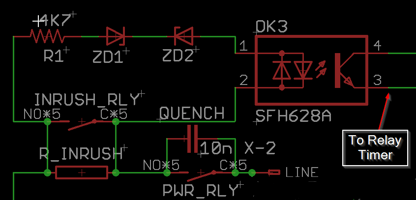
When the power is first engaged, the main power supply capacitors are drained completely, and so are essentially a short-circuit for a brief moment. At this moment, the voltage across the inrush power resistor is 120VRMS, or 170V peak, and this will drop as the capacitors charge. The LEDs in the opto-coupler will be on, because the voltage is high enough to pass through the zener diodes. Once the voltage across the inrush power resistor falls below 56V, (meaning the capacitors are mostly charged) the opto-coupler turns off, and the timer starts to close the relay. Under no circumstances will the relay try to close unless the current through the power resistor is low. There will be no excessive sparking of the contacts, and the capacitors will be soft-started in all scenarios.
There is a 1-second timer on the relay, but this has nothing to do with waiting for the capacitors to charge. It’s purpose is to prevent relay chattering in the case of intermittent power. The relays will not switch on and off with a frequency any higher than 1Hz under any circumstance, and I tested a lot of scenarios to prove this!
More details here at the product page.
Installation documentation is here. Please read through to be sure you are comfortable with this project.