


Here’s a method to make new cable assemblies by soldering instead of crimping. Two systems are shown; JST XH, as original in Adcom amplifiers, and a more premium option, Molex NanoFit.
This guide was written with Adcom amplifier restorers in mind, but applies to many zillions of applications for JST XH, or Molex NanoFit board-header systems.
Crimping is great too; You may prefer to just buy a crimping tool for JST XH type connectors. The tool is not expensive, and there are plenty of tutorials on the internet on how to crimp them. The Molex-branded crimping tool for NanoFit is $600, yikes, but I suspect a cheaper tool can be used. Let me know if you know.
Soldering them by hand is not too difficult, with a little practice, and produces an excellent, reliable result.
JST XH:
Part numbers:
Available at Mouser, Digikey, etc.
3-Pin Board Header B3B-XH-A(LF)(SN)
2-Pin Board Header B2B-XH-A(LF)(SN)
3-Pin plug housing XHP-3
2-Pin plug housing HXP-2
XH Crimp terminal SXH-001T-PO.6 (You may have to buy at least Qty100.)
You can re-use the original wires, or replace with your own 22AWG stranded wire.
Strip a very short piece of insulation off the wires and tin them. (Apply extra flux paste if the wire is corroded with age.)

Clip off the top third of these little bits of metal, so that it’s easier to fold them over into a circle. The crimp tool makes a deep U bend in each of these, so we’re cutting off a little excess for our purpose.

Hold the pin vertically with an alligator clip—so that solder does not flow by gravity into the mating surfaces—and apply a little blob of solder to this spot. Just that middle bit.

Melt the wire into the spot.

And crimp the collar thingy around the wire. This requires some finesse. It needs to be somewhat circular, not just pinched flat, to fit in the housing.


Observe the wire colors and order of pins on the old plug and the new, and insert the wires until they make a satisfying CLICK!

Nice!

Molex NanoFit:
The premium option. These are super nice, with gold-flashed contacts. Lever-release for low insert and removal force.
Part numbers:
3-Pin board header 105309-1203
2-Pin board header 105309-1202
3-Pin plug housing 105307-1203
2-Pin plug housing 105307-1203
NanoFit crimp terminal 105300-2200 (You may have to buy at least Qty100.)
You can re-use the original wires, or replace with your own 22AWG stranded wire.
Strip a very short piece of insulation off the wires and tin them. (Apply extra flux paste if the wire is corroded with age.)
Clip off the top half of these little pieces of metal on the terminal. This part is normally folded over and crimped by the tool. We will be putting a blob of solder here instead.

Hold the pin vertically with an alligator clip—so that solder does not flow by gravity into the mating surfaces—and apply a little blob of solder to the spot. Just that middle bit.

Melt the wire into the spot.

And crimp the collar thingy around the wire. This requires some finesse. It needs to be somewhat circular, not just pinched flat, to fit in the housing.


Observe the order of pins on the old plug and the new, and insert the wires until they make a satisfying CLICK!

The marking for Pin 1 on the Molex is microscopically small, and is in opposite relation to the key on the JST connector. The pin numbers go the opposite way. So, for minimum confusion with the JST footprint markings on the board, let’s just pretend that convention doesn’t exist, and orient the connectors so that the Molex keys match the JST system. Make sure you observe the position of the key, and get the wires in the same order. Push the wires in until they make a satisfying CLICK!
Nice!

Finally, clip off this little locating pin on the NanoFit board header.

And install to your board. Make sure the key lines up with the board markings for the JST header. (Dashed lines)
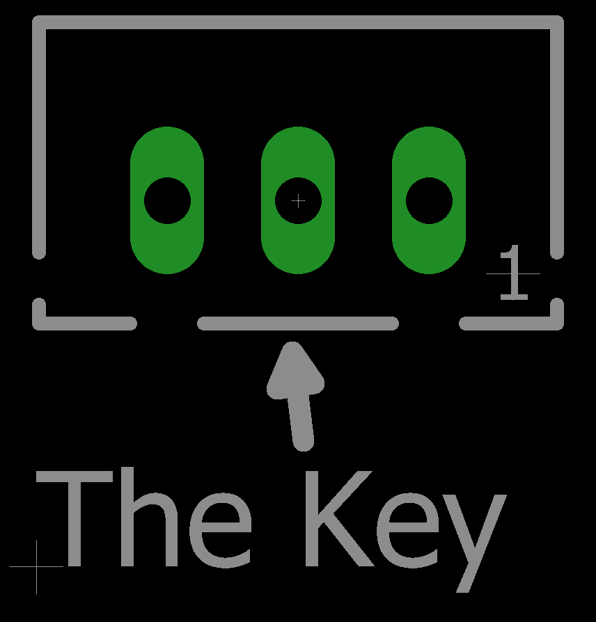

Minor annoyance for EBFA-565 users v2024.01.09 and earlier:
Unfortunately, these NanoFit connectors don’t have the same footprint as the original JST connectors. This causes physical interference issues for two of the connectors on the EBFA-565. It was not designed for NanoFit connectors. This will be corrected in future board revisions.
J104 needs to be installed at a jaunty angle.

And J103 needs to have its pins swapped, opposite how the original JST connector is made, so that the lever can be reached. Also, reverse the connector on the board to match. The “key” will now be opposite how it’s marked.


You could also pin-swap the J104 bias cable, so that the connector fits square. Just make sure you get your wires in the right order. One side’s bias cable will be in opposite pin order from the other.
You can verify this by checking the wire colors against this chart. On the bottom of the EBFA board, the bias connectors are labeled “B C E”, corresponding to the bias compensation transistor on the output module.
On the output modules, the colors also correspond to the transistor leads.
B = Brown
C = Red
E = Orange