Big news! I have completely re-designed circuit boards for the Adcom GFA-565. Based on customer feedback, I’ve made many improvements. These new boards are easier to install, harder to screw up, and they even perform a little better!
Buy them here. Hoppe’s Brain EBFA-565.

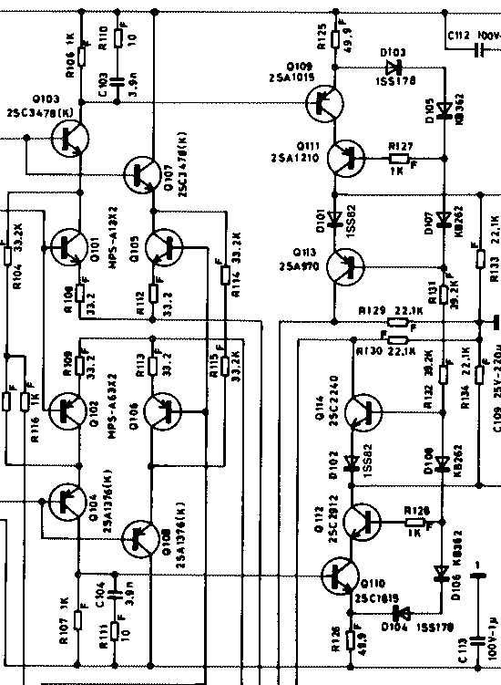
The GFA-565’s circuit—designed by the legendary Walt Jung—is a picture of perfect symmetry; A complementary mirror-image from positive to negative halves.

Unfortunately, the OEM circuit board layout doesn’t reflect this symmetry. Things are packed in kind of tight, and it’s kind of hard to follow.

I’m not trash-talking the original designers. The OEM board is a perfectly good design, but it’s single-sided, so compromises must be made in the layout, and they would have been under budgetary pressure to make it small, or to meet a certain size so they can fit a certain number of boards on a PCB panel. Thus, the OEM board is a bit cramped. The OEM board is designed for manufacturing. Hoppe’s Brain boards are designed for DIY.
Again—not complaining—Adcom’s circuit boards were better quality than similarly priced competition at the time.
The new layout reflects the symmetry of the circuit. It’s larger than the OEM board, and arranged in a more symmetrical fashion. Impedances seen by the circuit, that are caused by the board, are therefore more evenly balanced.
More features:
- Solder-less installation: Something I kept hearing from customers, is that if something goes wrong and the magic smoke escapes, and the board needs to come out for repair… All the wires need to be de-soldered, and it’s hard to reach them without burning components, wires, or chewing up the PCB pads. It’s a little awkward to work with the older board with so many solder connections, and a major bummer to have to re-do them every time the board needs to come out.
On the EBFA-565, all connections that used to be solder-pads, are now right up front on WAGO cage-clamp terminal blocks. These spring-loaded clamps grip the wire very, very firmly, and make an oxygen-tight connection that will never come loose. (Screw-terminal blocks can come loose over time as the copper squishes.) The board can be removed for troubleshooting or repair in a few minutes, and reinstalled with no damage to PCB pads. …so much better. And it makes the wiring neater too.

Inside a WAGO Cage-Clamp - Top-shelf components throughout: Kits and pre-assembled boards come with Dale RN and CMF resistors, 0.1% tolerance resistors in key locations, polypropylene capacitors, high-endurance electrolytic capacitors, silver-mica capacitors, etc… The good stuff.
- Compatible with old parts from the original board, so if you are building up from a blank board, you may recycle many of the un-damaged original parts. (With a few exceptions, see below)
- Two-layer, plated through-hole FR4 fiberglass circuit board.
- Traces are routed on the top and bottom layers.
- Ground planes cover the top and bottom layers.
- High-impedance traces are given wider isolation from ground planes, other traces and pads.
- Symmetrical layout makes it easier to build, and less error-prone, because it’s easier to locate the components.
- More room to work: Things are less crowded. It’s easy to probe any point on the board, and it’s easier to assemble and re-work.
- Clear labeling: Every component is labeled with its part number and value.
- An annotated schematic, loaded with troubleshooting tips, DC operating points, etc, is included with the board, printed on 11×17 paper. Download it here.

- Convenient test points for measuring the most important circuit parameters, referred to expected values on the schematic.

- Improved heatsinking. The TO-126 VAS transistors in the original design run very hot. The heatsinking of this new design is much more effective and keeps temperatures below 60C.
- Bypass caps are added to the +/-13.8V supplies
- A 0.1uF polypropylene bypass cap has been added in parallel with the 10 ohm isolation resistance between amp ground and the input section. This improves high-frequency coupling between these ground potentials. This feature was added in response to a customer who experienced oscillation because of substituting a wire-wound resistor in this position. The added inductance was causing the oscillation, and a metal-film resistor fixed the issue. If a little bit of inductance can cause this issue, I figured that adding a bypass cap in parallel with prevent that potential issue, and it may improve performance a smidge.
- Includes new cable assemblies for signal input, bias compensation transistors mounted on the heatsinks, and bias enable from the soft-start board. These cables are often corroded from capacitor leakage, or storage or operation in a humid environment. I had these cables custom-manufactured, as they are difficult to make by hand, and kind of essential for a good restore job.


Very nice work, as always!